Take a look around – do you see a surface that looks a little bumpy? Now close your eyes, reach out your hand, and feel that surface. Got an idea of what it feels like? Great! Now, could you use what you’ve learned with your sense of touch to draw a picture of this bumpy surface? Probably not. Creating three-dimensional images of surfaces like the one you just touched is a difficult task for a human, but is the specialty of one of the instruments I use, the atomic force microscope!

Atomic force microscopy, or AFM, measures the topography of a surface. In other words, it maps the heights of very small features on a surface. You can think of this like mapping the heights of mountains in a mountain range. Much like you could track your height above the Earth’s surface as you climb through a mountain range, an atomic force microscope tracks the heights of tiny features on a surface by, in a sense, walking across it.
AFM gives us information in three directions: x (length), y (width), and z (height). But what’s super awesome about this technique is the resolution that we can get – we’re actually able to distinguish height differences of less than one nanometer (one billionth of a meter)!
So how does this microscope actually work? It’s not exactly like the microscope you might have used in middle school science class. Instead, its main feature is a cantilever (like a beam secured at just one end) that has a very sharp probe tip on the end. This tip has a radius on the nanometer scale and is “dragged” over a sample to scan the heights of very small features. We can control the amount of interaction between the tip and the sample, and we keep this interaction force constant through the entire experiment. This is achieved by aligning a laser to the probe at the end of the cantilever; the laser reflects off the cantilever onto a mirror, which then reflects it onto a detector.

When scanning begins, the scanner starts to move in the x and y direction, allowing the cantilever and tip to trace the sample’s surface. As this happens, the laser light moves up and down on the detector. The more “bumpy” the sample, the more the laser light will move. This movement feeds back into the electronics of the instrument, which will then move the sample in the z direction to keep the amount of sample-tip interaction consistent. As a result, we will know the height (z dimension) of every point on our sample (x and y dimensions) based on how much the laser light position deviated from its original point. From this information we can create a visual picture of the topography of our sample!

Here in the Center for Sustainable Nanotechnology, we use AFM to help us answer many different questions about nanomaterials and their interactions with other systems, like cell membranes. We also use AFM to determine the size of the different nanomaterials that we use, but I mainly use it to study the interactions between supported lipid bilayers (a mimic for cell membranes) and various nanoparticles. One benefit of AFM is that we can perform experiments in fluids, which helps us to better model the natural environment. This means that our samples don’t have to stay dry, a requirement of many other imaging techniques.
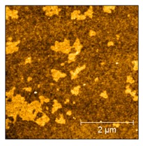
In our lab’s lipid bilayer studies, we first build a bilayer and take a “before nanoparticles” image with the AFM. We then introduce nanomaterials and scan the bilayer again to get an “after” image. This helps us to understand if and how many nanoparticles are interacting with the bilayer and if they are causing destruction to the bilayer. We can also see if the nanoparticles prefer to stick to some parts of the bilayers over others. For example, the image below shows a “before” bilayer that has three different components. The bright regions represent two components that sit about one nanometer higher than the major component of the bilayer, seen in the dark regions. AFM can tell us how these different parts of the bilayer orient themselves and if nanomaterials preferentially attach to some components over others. This helps us to understand how nanomaterials interact with real, living cells that also contain regions of different heights.

AFM is just one of the many techniques that we have access to as part of our collaborations across the CSN.1 Alone, it can help us to answer many questions, but combining the information we gain from AFM with different techniques really helps us to understand just how nanoparticles are interacting with bilayers and living cells. It’s just one tool in our toolbox to help us reach our goals!
REFERENCES (may need subscription for full access)
1. Troiano J.M.; Olenick L.L.; Keuch T.R.; Melby E.S.; Hu D.; Lohse S.E.; Mensch A.C.; Doğangün M.; Vartanian A.M.; Torelli M.D.; Ehimiaghe E.; Walter S.R.; Fu L.; Anderton C.R.; Zhu Z.; Wang H.; Orr G.; Murphy C.J.; Hamers R.J.; Pedersen J.A.; Geiger F.M. Direct Probes of 4-nm Diameter Gold Nanoparticles Interacting with Supported Lipid Bilayers, Journal of Physical Chemistry C, 2015, 119(1), 534–546. http://dx.doi.org/10.1021/jp512107z
(Read the public-friendly blog summary here.)

[…] the Center for Sustainable Nanotechnology to visualize nanoparticles and cell membranes, such as atomic force microscopy and super-resolution fluorescence […]